Overview
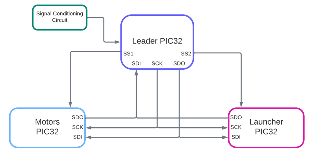
The Powerpuff Bot's electrical design featured 3 separate microcontrollers: 1 Leader PIC32 that used sensors as inputs for overall gameplay and 2 Follower PIC32's for controlling the drivetrain motors and launcher mechanism.
SPI Communication
Leader Controller
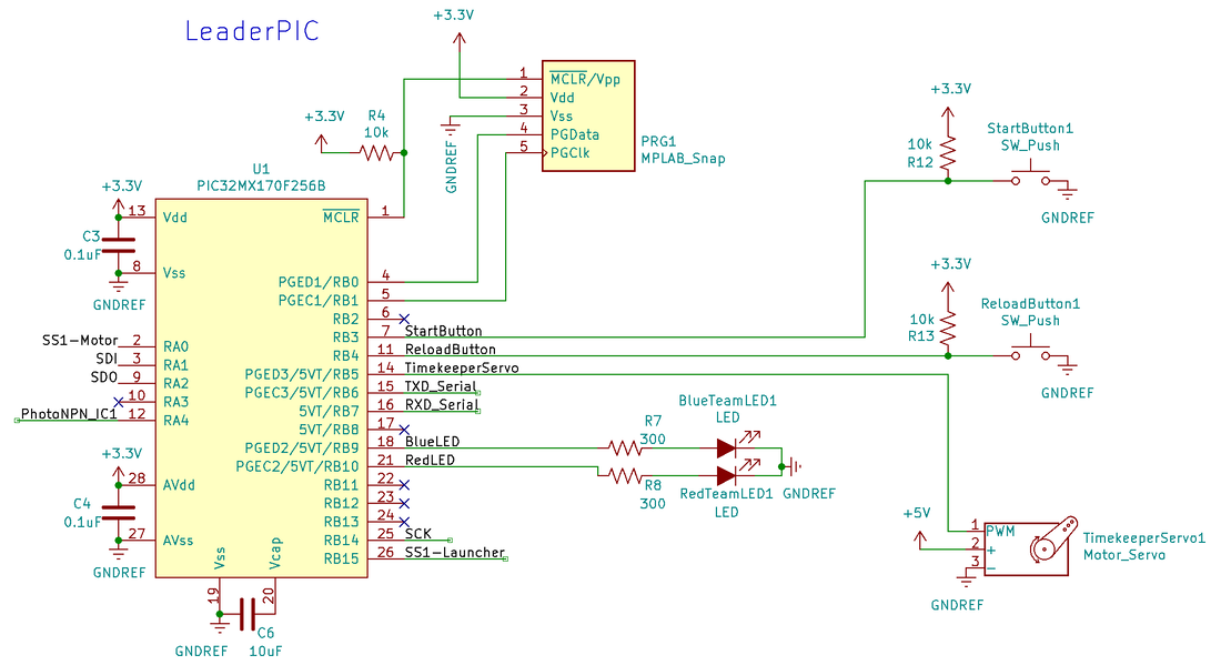
The Leader PIC has a simple circuit that includes only indicator LEDs, the timekeeping servo, and the two buttons. There are additionally lines for the SPI communication with the two other controllers. The two other controllers share an SDI and SDO, while the Leader manually lowers and raises the SS line associated with the appropriate PIC.
Signal Conditioning Circuit
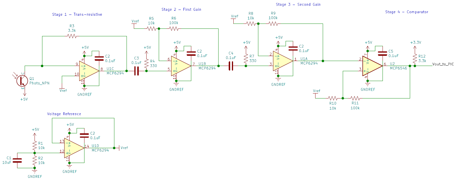
In order to detect the IR beacon from up to 8 feet away, we implemented the following circuit with a phototransistor. The output of this circuit was an input into the Leader PIC. The circuit featured the following stages:
1) trans-resistive stage to convert current from the phototransistor into a proportional voltage
2) first AC coupling and gain stage with a gain of 11
3) second AC coupling and gain stage with a gain of 11
4) inverting comparator with hysteresis to convert the signal into a digital signal for input capture into the Leader PIC
Motor Controller
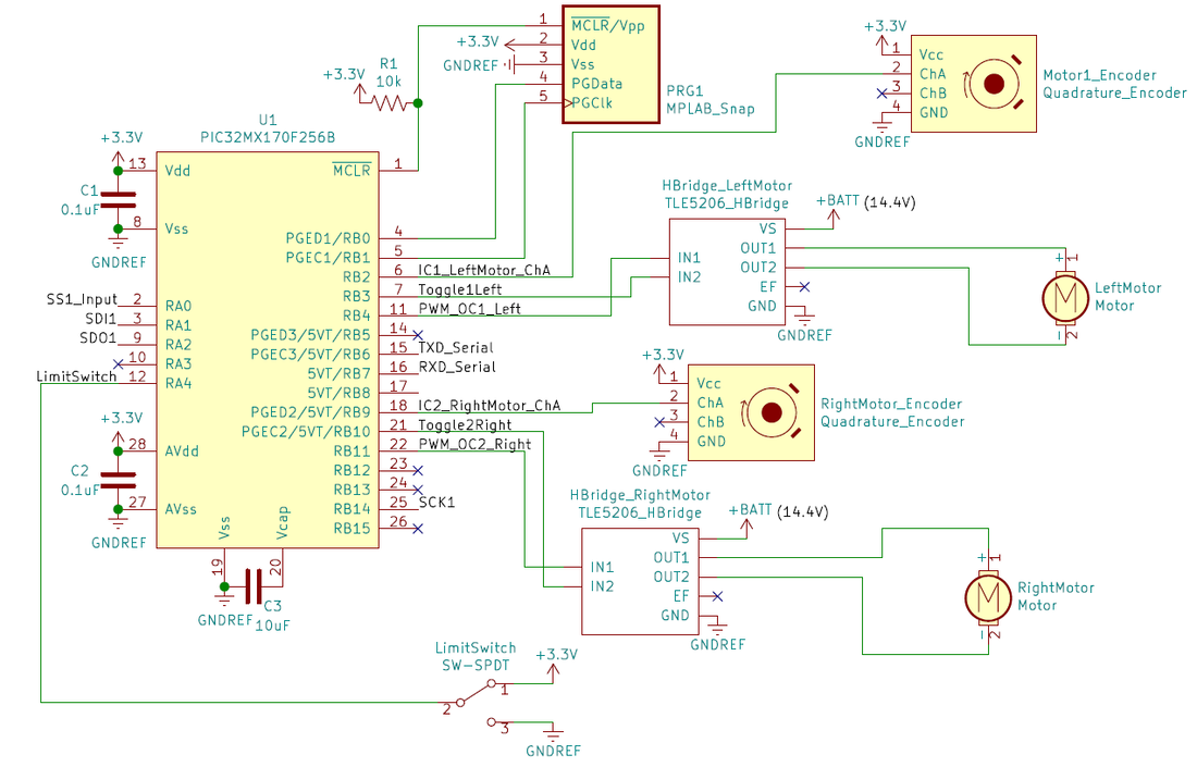
The motor PIC32 controlled the drivetrain motors with inputs from two quadrature encoders and a single pole double throw (SPDT) limit switch. The TLE5206 H-bridge drove each of the DC motors, which were powered via batteries (14.4 V). The PIC32 outputted a PWM signal and a toggle signal used to control the direction of the motors spinning as the inputs into the H-bridge. For speed control, a single channel from each quadrature encoder was used for input capture into the PIC32. Lastly, a limit switch was used to detect when the robot had fully reversed into the reload wall.
Launcher Controller
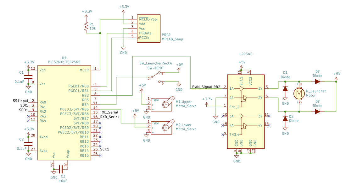
The Launcher PIC32 was one of two follower PICs, and controlled the mechanisms behind launching and reloading. RB3 and RB5 controlled the two reload servos, which would move in tandem to release the next ball into the launch position and advance the waiting balls through the reload tube. RB2 controlled the DC motor by providing a PWM signal to the L293NE driver, which in turn produced a signal for the launcher motor. Once the motor pulled the rack far enough backward, the rack would hit a limit switch that the launcher PIC detected on RB4, and when the limit switch was again released, we could tell the DC motor to stop rotating since a shot had successfully completed.
